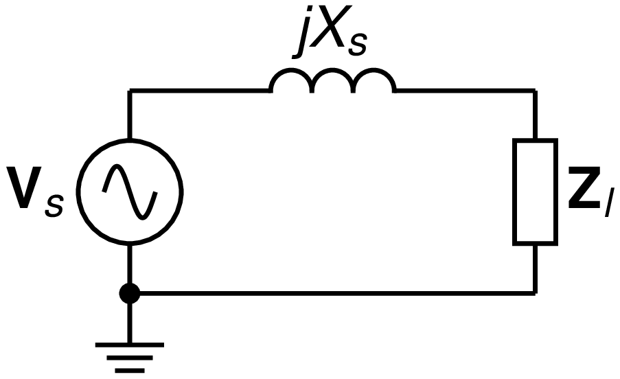
O: (0,0)

Vs: source(up_ dy from O,S); llabel(,\mathbf{V}_s,)
L:  inductor(right_ 2*dx,,3,,dimen_/5); llabel(,jX_s,)
Zl: ebox(down_ to (Here.x,O.y)); llabel(,\mathbf{Z}_l,)
    line to O
    dot
    ground
I fell in love with Circuit Macros in 2003, even before discovering the joys of Python in 2005. I worked as a lecturer for just over 20 years, teaching various subjects in electrical engineering, first at the Department of Electrical & Electronic Engineering at Stellenbosch University, and thereafter for the Electrical Engineering Technology programme of the Technical University of Denmark (DTU). During this time, I made more than 2,400 drawings using Circuit Macros. After four years now again working in industry, I find commercial tools still just not adequate enough for drawing circuit diagrams or diagrams in general and thus decided to revisit my old drawings and share how to use Circuit Macros to create beautiful typesetted drawings.
Professor Emeritus, Dwight Aplevich’s user manual for Circuit Macros starts with this quote:
It appears that people who are unable to execute pretty pictures with pen and paper find it gratifying to try with a computer.
Thomas K. Landauer, The Trouble with Computers, MIT Press, Cambridge, Massachusetts,
1995
Circuit Macros makes use of the GNU M4 macro [pre-]processor language to translate the “circuit macros” into PIC (markup language) developed by Brian Kernighan – also famous for developing the C programming language alongside Dennis Ritchie – in 1981, whilst working at Bell Labs. Professor Dwight Aplevich developed his own, to quote,
pic-like interpreter for producing high-quality line graphics in several formats
called Dpic to produce, and I quote again,
diagrams for documents, or web files
See the Dpic user manual.